A CPU, or Central Processing Unit, is the cornerstone of a computer responsible for executing instructions of a computer program . It performs various operations, such as arithmetic, logic, control, and input/output (I/O). To execute these operations, the CPU uses its different components.
One of the robust and indispensable components of the CPU is the arithmetic and logic unit (ALU). It carries our mathematical (addition, subtraction, multiplication, and division), logical (AND, OR, and NOT), and bit-shifting operations on binary data (0s and 1s).
Get ready to unravel the working of the ALU, its components, and its characteristics in this article.
What is an Arithmetic and Control Unit (ALU)?
An arithmetic and logic unit is a key component of a computer’s CPU. It is a digital combinational circuit embedded inside the CPU that performs arithmetic and logical operations on binary data. In short, it serves as a binary calculator for a computer.
Most microprocessor architecture has two parts of the ALU – Arithmetic Unit (AU) and Logic Unit (LU).
- The Arithmetic Unit (AU) executes mathematical operations like addition, subtraction, multiplication, and division. It can process both fixed-point and floating-point operations. Hence, certain processors feature more than one AU – one for fixed-point operations and the other for floating-point operations.
- The Logical Unit (LU) carries out bitwise operations, such as AND, OR, XOR, etc., on binary data.
Besides this, the ALU performs operations in an optimized manner, i.e., it significantly reduces the number of steps required to compute a specific operation.
We can find the ALU in most control units and logical circuits, including the CPU (Central Processing Unit) and GPU (Graphical Processing Unit).
Fetch-Decode-Execute - Perpetual Mechanisms

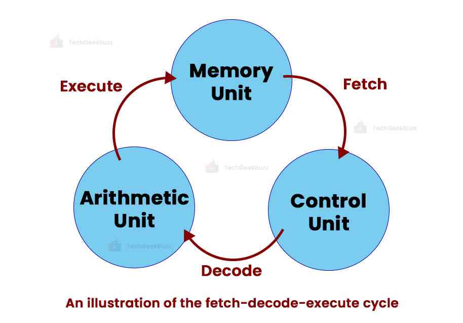
Fetch-decode-execute is a computational process and a continuous cycle that involves fetching instructions from a memory unit, decoding them into operations, and performing calculations. This basic cycle is the underlying mechanism for a modern computer’s complex behavior.
The fetch-decode-execute process involves different CPU components – Memory Unit, Control Unit , and Arithmetic and Logic Unit.
Let us discuss the fetch-decode-execute cycle in detail below.

1. Fetch (Memory Unit)
A memory unit is a CPU component that stores data and instructions required for computation. The CPU can retrieve the required data or instructions during the execution of a specific computer program.
2. Decode (Control Unit)
The control unit is the brain of the CPU. Upon receiving the instructions from the memory unit, the control unit decodes them to understand and interpret the meaning and ensure that the computer performs correct and accurate operations. Additionally, the control unit automates the fetch-decode-execute cycle.
3. Execute (Arithmetic and Logic Unit)
The ALU then receives the decoded instructions from the control unit, performs mathematical, logical, or bit-shifting operations, and stores the result in the computer memory .
The CPU further fetches the next instruction from the memory unit and executes it. This cycle continues until the CPU processes all instructions in a program.
How Does an ALU Work?
Let us now discuss the detailed working of the ALU below.
- Input/Output Access
The arithmetic and logical unit can directly access the control unit, main memory, input devices , and output devices . A CPU component called the bus, which is a shared electronic pathway, enables the efficient transfer of data between all these components.
- Instruction Word
An instruction word, or machine instruction word, is an input to the ALU consisting of an operation code (opcode), one or more operands, and sometimes a format code. The opcode instructs the ALU about the operation to be performed on operands, which are the data variables.
- Operation Execution
The ALU performs the specified operation (either mathematical or logical) on the operands. For instance, it is possible to add two operands, subtract them, compare them to determine the greater one, etc.
- Format Code
Sometimes, the instruction word comprises the format code combined with the opcode. It helps the ALU determine the type of the instruction word, whether fixed-point or floating-point.
- Output
The output of the ALU consists of two parts – the result and the status information. It stores the result in a storage register or accumulator. On the other hand, the status information indicates the success or failure of the operation. This information is stored in the machine status word .
- Storage and Flow
ALU has storage elements for storing input operands, intermediate results, and shifted results. Gated circuits control the flow of bits between different elements of the ALU.
Gate circuits are common elements of a digital system. They perform logical operations on one or more inputs and generate one output based on the logic rules.
- Sequence Logic Unit
A sequence logic unit (SLU) controls the sequence of operations performed by the ALU based on algorithms for each opcode. It identifies the flow of operations, activates the specific gates, and performs complex operations.
Operations Performed by the Arithmetic Logic Unit (ALU)
From the above discussion, you might have got an idea of what operations the APU can perform. Well, we shall talk about those ALU operations in detail here.
- Arithmetic Operations: Arithmetic operations refer to bit addition and subtraction. Multiplication and division are rarely used as they are expensive. Addition is used in place of multiplication, and subtraction is in place of division. These operations are useful for numerical computations.
- Logical Operations: A logical operation is a word or symbol that connects two or more phrases and tests whether their relationship is true or false. AND, OR, NOT, XOR, NAND, NOR, and XNOR are logical operations. The primary use of logical operations can be seen in decision-making.
- Bit-Shifting Operations: The ALU can shift binary bits to the left or right by a specific number of places. Bit-shifting operations come in handy while encoding, extracting bits, and manipulating data.
- Comparison Operations: The ALU can compare two binary values and determine the relationship between them, such as equality, greater than, less than, and inequality. These operations are useful in conditional branching, decision-making, and sorting algorithms.
Arithmetic Logic Unit (ALU) Signals
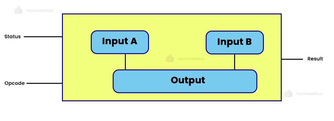
ALU is connected to many external electronic devices through input and output connections that transmit digital signals. Signals from external circuits serve as input to ALU. It processes those signals and transmits them to external electronics.
Here are the three major signals of ALU:

- Opcode
Opcode, or operation code, determines the type of operation the ALU will perform.
- Data
ALU has three parallel buses, each containing two input and output operands. These buses carry the same amount of signals.
- Status
Inputs
The ALU may require extra data or inputs after finishing an operation to continue. "Carry-in," a cached carry-out from the previous ALU function, is one often utilized input. The ALU may consider the carry propagation over several operations using this carry-in input, resulting in accurate results for the following calculations.
Outputs
The ALU generates a number of status outputs that contribute to the information available about the operation's outcome. General-purpose ALUs commonly handle these status signals.
- Overflow: The overflow signal lets you know if the operation's outcome is outside the acceptable range. It recognizes situations when the outcome cannot be precisely expressed with the bits at hand.
- Carry Out: The carry-out signal shows whether a carry occurred throughout the operation.
- Zero: The zero signal shows if the operation's outcome is zero. In future instructions or decision-making procedures, it aids in the detection of equality or particular circumstances.
- Negative: The negative signal lets you know whether the procedure has a bad outcome. It is frequently employed in signed arithmetic operations or for figuring out a number's sign.
ALU Configurations
Let us now explore different components with which ALU interacts.
1. Accumulator
An accumulator is a dedicated register that holds the result of the operations performed by the ALU. The ALU uses the result of a specific operation for its subsequent operations.
2. Instruction Set Architecture (ISA)
An instruction set architecture (ISA) is a set of commands and operations used by the software to communicate with the hardware. In other words, it is a set of commands the processor executes to process program instructions.
3. Stack
A stack is a data structure that stores data in the last-in-first-out (LIFO) manner. The ALU performs operations on the top elements of the stack. The top elements are popped out of the stack for calculation, and the results are again pushed to the stack.
4. Register Stack
A register stack is a stack-like architecture consisting of dedicated registers. The ALU pushes and pops values from these registers, resulting in efficient temporary storage during computation and data manipulation.
5. Register to Register
In this configuration, ALU uses data stored in registers for computation. It accepts input from a specific register, performs operations, and stores the result in another register. This enables efficient data movement and manipulation between registers.
6. Register Memory
The register-memory configuration enables the interaction of ALU with the computer’s main memory. Data that is retrieved from or stored in memory locations is processed by the ALU in relation to data that is stored in registers. Load/store instructions frequently employ this arrangement when transferring data between registers and memory.
Advantages and Disadvantages of ALU
Here are some remarkable advantages and a few drawbacks of the ALU:
Advantages
- ALU performs complex operations in a short time frame.
- It enables quick data processing and instruction execution.
- It handles a wide range of operations, including mathematical, logical, bitwise, comparison, and shifting operations.
- ALU executes instructions optimally, reducing the number of steps required to perform each instruction.
- It supports concurrent execution of multiple instructions, resulting in enhanced system performance.
- ALUs are compact in size, making them ideal for modern computer systems. Hence, they can be embedded into integrated circuits (ICs).
Disadvantages
- ALU can perform only those operations specified by the CPU and instruction set architecture.
- The rounding-off capability results in reduced precision.
- The architecture of ALU is difficult to understand, and the concept of pipelining is challenging to grasp.
- There are inconsistencies in latencies.
Conclusion
This was all about the Arithmetic Control Unit (ALU). It is one of the major components of the CPU, responsible for executing mathematical, logical, and bit-shifting operations.
Through this article, we have explained the working of the ALU, operations performed by ALU, its configuration with other components, and signals. If you have any doubts regarding ALU, let us know in the comments below.
People are also reading:


![What is an Assembler? [Definition, Working, & Types]](/media/new_post_images/What_is_Assembler.jpg)
![What is I/O? [Types, Examples, & Methods]](/media/new_post_images/What_is_I_O.webp)

Leave a Comment on this Post